Saturday, September 16, 2006
Questor Continues
Well, the weekend is here, but my wife isn't, so I've got the place to myself for a couple of days. I may as well work on my airplane.
I was working on figuring out how to get the power lines connected to the tail section for the lights in the horizontal stabilizer, and I think I came up with an awesome solution. I originally was just going to have wires running between the laminations and exiting out through some exit point, but I figured there is a possibility that over time, or in the event of a mishap, the wires could break at the exit point, making it impossible to reconnect them.
So, I thought of running some kind of wide metal conductor between the laminate and simply drilling a hole down to expose the conductor so that I could solder a wire directly to it. That way, if the wire ever broke off or became severed, all I would need to do is solder in a new wire.
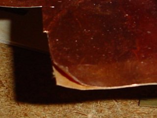
The solution was this stuff:

This is a sheet of very thin peel and stick copper sheeting, presumably used primarily in stained glass work. All I need to do is cut a strip to the size I need, stick it down between the laminated pieces, and I'm done. I constructed a test piece to determine if the idea would work, and it worked beautifully!.

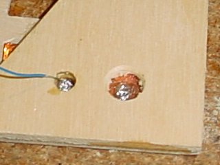
I drilled two holes, because I didn't know if I was going to be able to effectively solder within the smaller hole. But it turns out it wasn't a problem at all. This was just the answer I was looking for. This fixes the big question mark for the horizontal stabilizer, so now I just need to work out something similar for the tail boom. There will be a connector coming from the boom to mate with a connector in the stabilizer once it's all done. I hope to complete a good portion of the tail this weekend.
I think I'll start by getting some sleep!
I was working on figuring out how to get the power lines connected to the tail section for the lights in the horizontal stabilizer, and I think I came up with an awesome solution. I originally was just going to have wires running between the laminations and exiting out through some exit point, but I figured there is a possibility that over time, or in the event of a mishap, the wires could break at the exit point, making it impossible to reconnect them.
So, I thought of running some kind of wide metal conductor between the laminate and simply drilling a hole down to expose the conductor so that I could solder a wire directly to it. That way, if the wire ever broke off or became severed, all I would need to do is solder in a new wire.
The solution was this stuff:

This is a sheet of very thin peel and stick copper sheeting, presumably used primarily in stained glass work. All I need to do is cut a strip to the size I need, stick it down between the laminated pieces, and I'm done. I constructed a test piece to determine if the idea would work, and it worked beautifully!.

I drilled two holes, because I didn't know if I was going to be able to effectively solder within the smaller hole. But it turns out it wasn't a problem at all. This was just the answer I was looking for. This fixes the big question mark for the horizontal stabilizer, so now I just need to work out something similar for the tail boom. There will be a connector coming from the boom to mate with a connector in the stabilizer once it's all done. I hope to complete a good portion of the tail this weekend.
I think I'll start by getting some sleep!


2 Comments:
At 16/9/06 3:29 AM, Tracey said…
Sleep is usually a good thing Bill! Neat idea about the copper conductor. That was a really unique solution :)
At 16/9/06 9:28 AM, Jude said…
Wow I not only understood that, but it was an awesome idea Bill. Good for you! Have you ever thought of being an inventor? You have the mind for it, dude. ;-)
Hope you got lots of sleep, enjoy the weekend!
Post a Comment
<< Home