Saturday, September 16, 2006
Tale of Questor's Tail
Gather 'round kids and let me tell you the tale of Questor's tail. Today's progress, anyway.
I have a problem I have not yet worked out a final solution for, and that is connecting the lights in the horizontal stabilizer to the power rails in the tail boom. However, I proceeded ahead with my original plan and will probably just implement a connector I will have to plug in, manually, unless and until I have another aha moment.
I called up a friend of mine to bounce some ideas off of. Actually, he called me, but I sent him a message in ICQ first. :) After we tossed some ideas around for a while, tossing most of them out, we finally came to a solution that my friend said that I had suggested to him at some point in the past (and it would have probably saved me a lot of time had I remembered this particular suggestion). He said, why not mount the LEDs on the fuselage, externally (in my case, on the tail boom) and simply aim them at the tail? In other words, instead of going through jars of Excedrin PM to get the thing to light up from the inside, I could simply light it up from the outside.
Brilliant! (no pun intended...ok, yes it was)
Well, that would be the easy solution. Really, it would. But, being the complicated person that I am, I decided to press on with the current design. After all, I had already cut out all the frickin' pieces!!!
Progress was extremely slow going in the beginning. I made a couple of false starts, which cost me an hour here and there. I neglected to mark all the places where holes needed to be drilled, hinges needed to be inserted, etc., but at least I didn't do anything irreversible and was able to drop back and restart without killing anybody.
I can't even remember what all transpired to make things go so slowly. I guess there was just a lot of testing of ideas going on. One test failed, at least temporarily, then I thought of a tool that I could make to fix the problem that made the test fail, so I was happy about that. It involved a method of preventing the thin sticky-back copper strips from coming off when I soldered the LED wires to them. I figured that out pretty quickly and was able to move on.
I used an old dried up ball point pen to make traces (tiny canals) in the balsa wood for the LED wires to run along so that when the layers are laminated together, they would press flush together. At some point, the pen started working again, so that was kind of annoying. Luckily, I had another old dried up ball point pen that I used to finish the job. It makes perfect little trenches in the wood for the tiny wires to sit down inside.
Most of the time spent on this stupid (can I say stupid?) project is in thinking about this thing in three dimensions and trying to figure out where everything goes without getting in the way of something else. It turns out, I have very little wiggle room in this tail and it has been far more complicated than I ever anticipated. I only wish I had thought or (rather, REMEMBERED) the external lighting solution in the beginning, since then I could have built this tail in a weekend. Who would have thought that running a couple wires to the tail and installing six LEDs would be such a pain in the tail section? I guess I should have.
Anyway, how about some pictures! I know they're kind of small, but I'm low on disk space, so can't host larger ones at the moment.
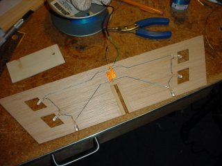
Here's the upper laminate of the horizontal stabilizer with all the LEDs installed. The blue wires are all run along the little canals I dug with the ball point pen, and you can see the two peel-and-stick copper strips at the top (which is really the rear of the part).
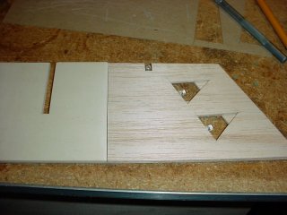
Here I have placed a couple of the lower laminate pieces over the assembly (the bottom is facing the camera) to show kind of how the final product will look. The tail will be covered with MonoKote, so the light from the LEDs will show through the covering. I cut out triangles on the lower laminate, and parallelgrams on the upper laminate (which is underneath in this picture, since the part is turned over). That way, I can tell the difference between the top and the bottom of the aircraft if I happen to lose orientation in the night. One LED faces straight forward, which is always helpful from many angles, especially during night landings (the plane is hardest to see at night when it is coming straight at you).
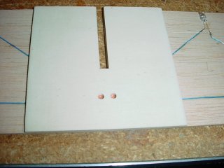
And here is the implementation of the idea I had the other day (yesterday?). I have drilled two holes in the mounting plate for access to the copper strips so I can wire the thing up once I get it all together.
OH MY GOSH! How could I have forgotten this? I just remembered what took so much time this morning - why things got off to such a slow start (besides going down to Cingular to get my SIM card upgraded and to drop off my late rent check). I had to select the LEDs to use on the plane!
I wanted to use LEDs that were closely matched throughout the plane, and I needed 27 LEDs for the entire project. I set up a test station to plug in the LEDs and measure their forward voltage drop. I tested probably 400 LEDs, and piled them in separate piles, depending on the voltage readings. Once that was all done, I took the biggest pile and re-tested them, breaking them into smaller piles, depending on voltage readings (a finer breakdown). Once that was done, I picked 27 LEDs that were about as closely matched as I could get (considering my setup).
After I had my LEDs chosen, I put all the piles of LEDs into separate little ziplock baggies and labelled them, so I won't have to go through this lengthy process again in the future. Man, that took a long time, but I think it was worth it. Six of the LEDs are now mounted in the tail! Woo hoo! Only 21 more to go!
Sigh.
I still have a long, long way to go on the tail, and an even longer route ahead of me when I finally ever get to build the wing. Right now, I am working on the mounting plate (above), which is the center part of the lower laminate of the horizontal stabilizer - it is the piece that will hold the stabilizer to the tail boom, once that is built. I've got some tricky hole drilling and cutting to do, and I haven't quite worked out the tooling sequence I need to make this work out right, yet. It's a jigsaw puzzle. I find myself making tools half the time just to make the pieces I need. I guess that's part of the art of woodworking.
I am learning a lot, that's for sure. I picked up a couple of excellent books on this stuff and am reading all about paint and finishing now, so when I get to that point, I'll be armed with some new knowledge. I went to a class the other day on how to improve your memory, and I am practicing the techniques and it seems to be working. I am confident that now I won't forget this stuff when it comes time to use it. I'm even thinking of using this one book as the first book that I memorize. Yes, it is possible to memorize an entire book - even word for word if you want to go to that level - but that's a subject for another blog...or a book or something.
By the way, I learned 14 words in Spanish during this three-hour memory class - and that was just one exercise. I still remember the words (though I can't spell them), as well as the names of the 21 other people in the class. Cool beans, Maynard!
Anyway, back to work. Er, uh, well maybe it's back to bed. Rats! Weekends are TOO SHORT!!!
Oh, man, I just realized I'm hungry. Did I eat today???
Please send food!
UPDATE:
Here's a few more pictures for you:
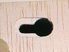
The horizontal stabilizer will be secured to the tail boom via four 10-32 nylon bolts. This is a sample of what the lock-down slots will look like - kind of like what you might find on the back of an average power strip.
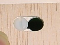
Here's what it will look like when it is secured to the mount with a nylon bolt.
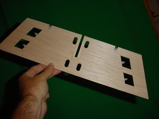
I have gone ahead and cut the clearance holes in the upper laminate for the horizontal stabilizer. The mounting plate seen earlier will get the tricky holes cut into them, like the kind you see on the back of an average household power strip (or wall-mounted telephone). I have no idea what the name is for that kind of hole.
Now I'm going to bed. It's almost 3:00 a.m.
I have a problem I have not yet worked out a final solution for, and that is connecting the lights in the horizontal stabilizer to the power rails in the tail boom. However, I proceeded ahead with my original plan and will probably just implement a connector I will have to plug in, manually, unless and until I have another aha moment.
I called up a friend of mine to bounce some ideas off of. Actually, he called me, but I sent him a message in ICQ first. :) After we tossed some ideas around for a while, tossing most of them out, we finally came to a solution that my friend said that I had suggested to him at some point in the past (and it would have probably saved me a lot of time had I remembered this particular suggestion). He said, why not mount the LEDs on the fuselage, externally (in my case, on the tail boom) and simply aim them at the tail? In other words, instead of going through jars of Excedrin PM to get the thing to light up from the inside, I could simply light it up from the outside.
Brilliant! (no pun intended...ok, yes it was)
Well, that would be the easy solution. Really, it would. But, being the complicated person that I am, I decided to press on with the current design. After all, I had already cut out all the frickin' pieces!!!
Progress was extremely slow going in the beginning. I made a couple of false starts, which cost me an hour here and there. I neglected to mark all the places where holes needed to be drilled, hinges needed to be inserted, etc., but at least I didn't do anything irreversible and was able to drop back and restart without killing anybody.
I can't even remember what all transpired to make things go so slowly. I guess there was just a lot of testing of ideas going on. One test failed, at least temporarily, then I thought of a tool that I could make to fix the problem that made the test fail, so I was happy about that. It involved a method of preventing the thin sticky-back copper strips from coming off when I soldered the LED wires to them. I figured that out pretty quickly and was able to move on.
I used an old dried up ball point pen to make traces (tiny canals) in the balsa wood for the LED wires to run along so that when the layers are laminated together, they would press flush together. At some point, the pen started working again, so that was kind of annoying. Luckily, I had another old dried up ball point pen that I used to finish the job. It makes perfect little trenches in the wood for the tiny wires to sit down inside.
Most of the time spent on this stupid (can I say stupid?) project is in thinking about this thing in three dimensions and trying to figure out where everything goes without getting in the way of something else. It turns out, I have very little wiggle room in this tail and it has been far more complicated than I ever anticipated. I only wish I had thought or (rather, REMEMBERED) the external lighting solution in the beginning, since then I could have built this tail in a weekend. Who would have thought that running a couple wires to the tail and installing six LEDs would be such a pain in the tail section? I guess I should have.
Anyway, how about some pictures! I know they're kind of small, but I'm low on disk space, so can't host larger ones at the moment.
Here's the upper laminate of the horizontal stabilizer with all the LEDs installed. The blue wires are all run along the little canals I dug with the ball point pen, and you can see the two peel-and-stick copper strips at the top (which is really the rear of the part).
Here I have placed a couple of the lower laminate pieces over the assembly (the bottom is facing the camera) to show kind of how the final product will look. The tail will be covered with MonoKote, so the light from the LEDs will show through the covering. I cut out triangles on the lower laminate, and parallelgrams on the upper laminate (which is underneath in this picture, since the part is turned over). That way, I can tell the difference between the top and the bottom of the aircraft if I happen to lose orientation in the night. One LED faces straight forward, which is always helpful from many angles, especially during night landings (the plane is hardest to see at night when it is coming straight at you).
And here is the implementation of the idea I had the other day (yesterday?). I have drilled two holes in the mounting plate for access to the copper strips so I can wire the thing up once I get it all together.
OH MY GOSH! How could I have forgotten this? I just remembered what took so much time this morning - why things got off to such a slow start (besides going down to Cingular to get my SIM card upgraded and to drop off my late rent check). I had to select the LEDs to use on the plane!
I wanted to use LEDs that were closely matched throughout the plane, and I needed 27 LEDs for the entire project. I set up a test station to plug in the LEDs and measure their forward voltage drop. I tested probably 400 LEDs, and piled them in separate piles, depending on the voltage readings. Once that was all done, I took the biggest pile and re-tested them, breaking them into smaller piles, depending on voltage readings (a finer breakdown). Once that was done, I picked 27 LEDs that were about as closely matched as I could get (considering my setup).
After I had my LEDs chosen, I put all the piles of LEDs into separate little ziplock baggies and labelled them, so I won't have to go through this lengthy process again in the future. Man, that took a long time, but I think it was worth it. Six of the LEDs are now mounted in the tail! Woo hoo! Only 21 more to go!
Sigh.
I still have a long, long way to go on the tail, and an even longer route ahead of me when I finally ever get to build the wing. Right now, I am working on the mounting plate (above), which is the center part of the lower laminate of the horizontal stabilizer - it is the piece that will hold the stabilizer to the tail boom, once that is built. I've got some tricky hole drilling and cutting to do, and I haven't quite worked out the tooling sequence I need to make this work out right, yet. It's a jigsaw puzzle. I find myself making tools half the time just to make the pieces I need. I guess that's part of the art of woodworking.
I am learning a lot, that's for sure. I picked up a couple of excellent books on this stuff and am reading all about paint and finishing now, so when I get to that point, I'll be armed with some new knowledge. I went to a class the other day on how to improve your memory, and I am practicing the techniques and it seems to be working. I am confident that now I won't forget this stuff when it comes time to use it. I'm even thinking of using this one book as the first book that I memorize. Yes, it is possible to memorize an entire book - even word for word if you want to go to that level - but that's a subject for another blog...or a book or something.
By the way, I learned 14 words in Spanish during this three-hour memory class - and that was just one exercise. I still remember the words (though I can't spell them), as well as the names of the 21 other people in the class. Cool beans, Maynard!
Anyway, back to work. Er, uh, well maybe it's back to bed. Rats! Weekends are TOO SHORT!!!
Oh, man, I just realized I'm hungry. Did I eat today???
Please send food!
UPDATE:
Here's a few more pictures for you:
The horizontal stabilizer will be secured to the tail boom via four 10-32 nylon bolts. This is a sample of what the lock-down slots will look like - kind of like what you might find on the back of an average power strip.
Here's what it will look like when it is secured to the mount with a nylon bolt.
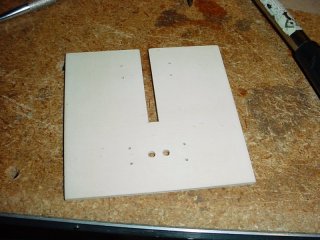
I have gone ahead and cut the clearance holes in the upper laminate for the horizontal stabilizer. The mounting plate seen earlier will get the tricky holes cut into them, like the kind you see on the back of an average household power strip (or wall-mounted telephone). I have no idea what the name is for that kind of hole.
Now I'm going to bed. It's almost 3:00 a.m.
posted by Bill @ 11:47 PM
![]()


3 Comments:
At 17/9/06 12:41 AM, Angel Feathers Tickle Me said…
Love to all....
At 17/9/06 2:52 AM, Bill said…
And to all a good night.
At 17/9/06 8:52 AM, Jude said…
Wow you're really going to town on this Bill! So did you eat?? I tried to send you food but they turned it back at the border. Seems the borscht all spilled out and made a mess. LOL
I laughed out loud about the dried up pen that decided to start working again. They NEVER do that when you WANT them to!!
And you may have very little wiggle room in your tail section, but there is plenty in mine!! Seriously, this is interesting to watch, you could write a book on how to do this, complete with the great pictures you show as graphics. Good job Bill!!!
Post a Comment
<< Home